|
||||||||||
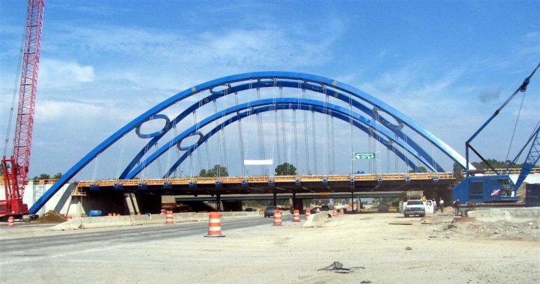
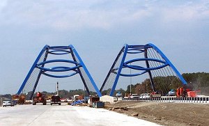
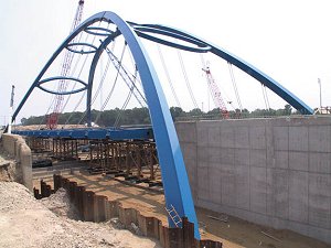
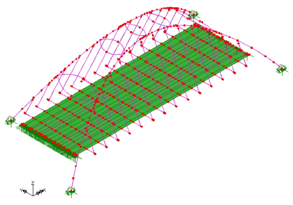
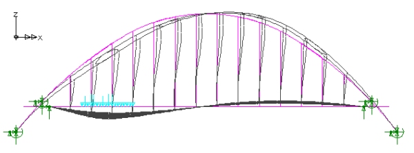
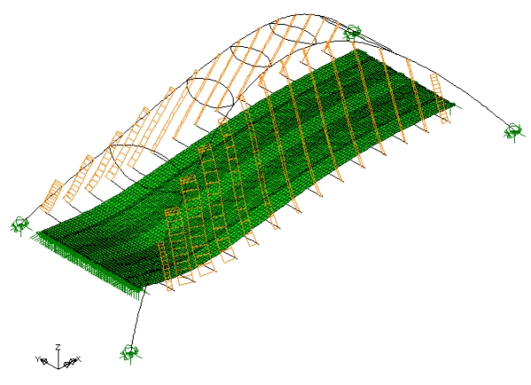
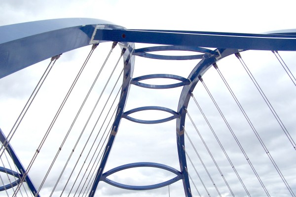
In order to restrain the bases of the arch ribs at their relative locations, a number of design options were investigated. This eventually resulted in the selection of a true arch design having fixed bases. Because the soil profile at the site consists of medium to soft clay that will creep under the arch longitudinal thrust force, it was decided to provide a foundation tie system that was independent of the soil. Exterior arch ribs are restrained longitudinally by 289� long, 7'-4" wide by 3'-2' deep concrete ties located 4 feet below the Telegraph Road roadway. Interior arch ribs both share the same 232 feet long, 14�-10 by 3�-2" longitudinal central concrete tie. Transverse ties, 11'-6" long, connect the exterior arch rib foundations to the abutment foundations. Ties are designed to resist the total arch thrust forces, but for redundancy reasons, several piles under the arch rib foundations are battered to help resist some of the arch thrust. Steel reinforcement in the ties is designed to resist the total arch thrust force, while maintaining maximum tensile stresses in the reinforcement of 24 ksi. Frictional resistance to the arch thrust between the foundation tie and the soil is also ignored in the design - increasing the redundancy of the foundation system. The bridge deck comprises a series of floor beams, stringers and stiffening girders. Transverse floor beams, supported by hangers, carry a 9" thick concrete deck. Longitudinal stringers and stiffening girders help reduce the deck deflection due to live load. The stiffening girders also distribute the live load between the adjacent hangers and this results in lighter hangers. Each hanger assembly consists of two strands of 2 1/8" diameter, ASTM 586 structural strand. Each strand within the assembly is designed to carry the total load of any adjacent failed strand with an impact factor of 2. Modelling with LUSAS The geometry of the two bridges required detailed structural analyses to investigate their behavior under different loading conditions. LUSAS Bridge was selected for this task and proved vital in determining the final profile of the arch ribs. Thick beam elements were used for meshing the ribs, top bracing, hangers, and floor framing system, while thin shell elements were used for discretizing the concrete deck slab. This 3D model enabled the global behavior of the bridge to be examined as well investigating the behavior of its separate structural components. The ability to name and group together structural features in LUSAS was particularly useful for this.
Dr Hiba Abdalla, Senior Designer at Alfred Benesch explains: "Using LUSAS, the arch ribs were optimized for minimum bending stresses under dead loads. Starting from a basic circular profile with constant radius, the profile radius was varied and the model re-analyzed until bending stresses were observed to attain a practical minimum. The resulting profile is an arch with a higher rise and two different radii, one for the crown segment and the other for the two outer landing segments. The arch optimization phase was greatly enhanced by the result processing facilities in LUSAS and the ease with which the geometrical outline of the structure could be manipulated." Results obtained Once the final geometry was decided, extensive LUSAS analyses examined the bridge performance under live, wind, and temperature loads, and all combinations thereof. Due to the unusual geometry of these bridges, live load effects at numerous locations along the arch ribs, transverse girders and longitudinal girders, had to be determined. The Autoloader vehicle load optimization facility, which identifies worst-case vehicle loading positions, coupled with influence analysis capabilities of LUSAS help speed up this repetitive task enormously. LUSAS animations of bridge displacements from moving live loads gave a better understanding of how the different components work together to carry traffic loading. Linear buckling analyses were also carried out to determine load factors. Since structural strands are used for hangers, it was crucial to accurately determine the force levels within each hanger during and after construction. LUSAS analyses examined hanger forces under dead loads, and helped determine the necessary stressing forces to be applied in order to maintain the bridge at its proposed profile grade. This technique proved to be very useful in predicting and accounting for displacements that occurred during construction.
"The arch optimization phase was greatly enhanced by the result processing facilities in LUSAS and the ease with which the geometrical outline of the structure could be manipulated." Dr Hiba Abdalla,
Senior Designer, Alfred Benesch
|
|
Software Information
|
||||||||
|