More
information
on
"force
per unit width"
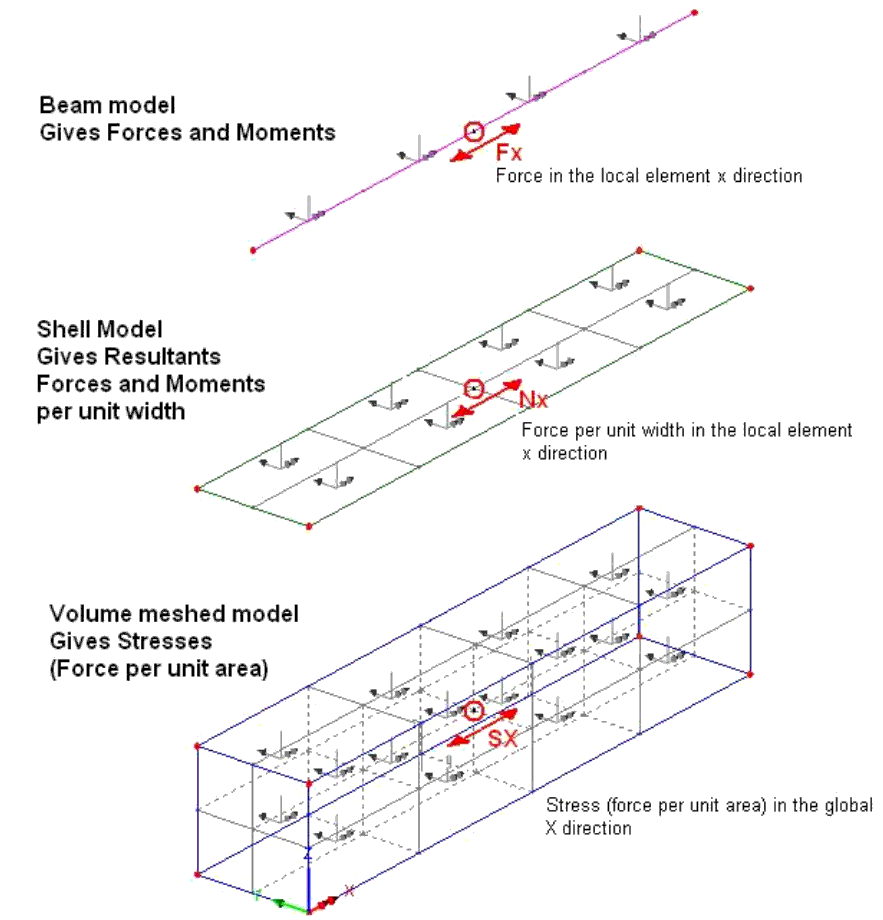
The
example illustrated below shows a comparison of the different
results obtained between a beam model, a shell model and a volume
meshed model:

For
the beam the cross-section properties are defined in a geometric
attribute. The force
obtained at a node represents the resulting force for the
cross-section.
In
the Volume meshed model, the width and depth of the cross-section
are modelled in the elements and stresses are obtained at each
node. The stress at a
node is a force per unit area at that discrete location. To obtain a force comparable with the beam model, the
stresses would have to be integrated with respect to the width and
depth of the cross-section.
When
looking at resultant forces, the shell model is part way between
the two with the width modelled by shell elements, but the
thickness is defined by a geometric attribute. Now Nx can be obtained as a force per unit width at each
node across the width (width is in the local y direction in the
example above). If Nx
is divided by the element thickness, an average stress will be
obtained. In LUSAS direct
stresses due to both membrane and flexural deformation are also
available for shell elements at Top, Middle and Bottom locations
through the thickness.
The
resulting force in the x direction for a shell element model is
the integral of Nx with respect to the width. This can be
obtained using by selecting the menu item: Utilities
>
Slice Resultants
Beams/Shells
A
line is drawn across the model to define a path to slice normal
to, and through, the model. With
this tool, the equivalent axial force in the x direction is
determined by integrating the stresses.
For
further information please see:
Modeller Reference Manual >
Chapter 8 - Viewing the Results > Manipulating the Results
Model > Beam Stress Resultants from
Beams and Shells
Please
also see the worked example:
Section Slicing of a 3D Shell Structure
|