User Area > Advice
Point/ Patch Loads (Discrete loads)
-
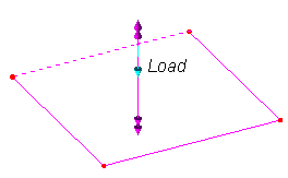
Discrete loads are assigned to
POINT features. These point features do not need to be part of the structure;
the point feature simply represents the position 0,0,0 in the loading
attribute definition. This is contrary to other "Structural loads"
(concentrated, locally distributed, body force, etc.), which must be assigned to a feature that is fully part of
the model and is meshed appropriately, such that the loads are
applied directly to the underlying elements of the feature.
-
Discrete loads
may be applied to structures which lay in any plane.
-
Modeller automatically translates
the projected discrete loads into equivalent nodal loads (concentrated loads).
It carries this process out when it creates the LUSAS datafile
(*.DAT) using the element
shape functions, and using search areas.
-
The
area of a model to which a discrete load is applied may be
restricted using SEARCH AREAS (Attributes>Search Area). For example, a search
area may be used to ensure that a discrete load placed on top of a
multi-storey building is applied to the roof only, by defining a
search area attribute and assigning it to the features which make
up the roof. In this example, illustrated below, the
building frame is modelled with beam elements and a search area is
assigned to the lines at the top of the model.
-
If no
search area is specified when the loading
assignment is made, Modeller will assume that all of the model
may potentially receive the applied loadings.
This may cause ambiguity when applying the loading and
may result in the load being applied to the wrong region of
mesh. If the multiple intersections of the load projected
onto mesh are possible, then this is reported in the Text Output
Window with reference to the load which will thus have no effect
on the mesh.

Rules
for search areas:
-
If
the model consists of line features (as in a grillage),
they must form closed boundaries (for surface-based models
there is no such requirement).
-
These
boundaries will form "bays" which may have a
maximum of 30 elements circumscribing the 3 or more "bay"
sides.
It is usually unnecessary to have
anywhere near 30 elements per bay, though this will depend
on the shape of the bay and the accuracy (and mesh
density) of the elements being used. When using
GRIL elements to model a grillage often no more than 4
elements would be required as these elements allow a
quadratic variation of moment and linear variation of
shear along their length. This limit can be adjusted
by manually setting the system variable called "SareaMaximumCellEdges",
if necessary.
More
on using discrete loads on a 2D frame/ beam model
The
following GRILLAGE and FRAME examples indicate the requirements
diagramatically.
1. Grillage :-
2. Frame :-
| This is not
a closed boundary system. |

|
|
|
| This
is a closed boundary. A line
is created and assigned with a "null" line mesh
(shown dashed), with an element type set to
"none" and 1 mesh division specified. This
encloses the SEARCH AREA. |
 |
More
on using discrete loads on a 2D frame/ beam model
|