Case Study
Analysis
of Barge Gate and Gate Abutment Structures
-
Optimization
of steel plate flood defence gates in New Orleans
-
Noticeably
faster modelling and analysis with LUSAS than previously
obtained
-
Tight design
schedule met

INCA
Engineers Inc. based in Bellevue, WA, is using LUSAS Civil
and Structural to assist with the design of flood protection
structures on two contracts awarded to it by the United States Army
Corps of Engineers (USACE), New Orleans District. By using LUSAS to
help with the design of a floating barge gate and associated
abutment structures the gate design could be optimized to meet
design criteria and a tight design schedule could be met.
|
Overview
On
29th August 2005, Hurricane Katrina, an extremely large and powerful
storm, overwhelmed the flood and storm defences at several locations
in and around New Orleans causing large-scale loss of life and
extensive damage to property. To help prevent future flooding the
hurricane protection system of levees, pump stations and flood gates
that encircle the most at-risk parts of the city is being
strengthened to create a stronger, flood and storm reduction system
that will give a once-in-100-years level of protection.
|

|
INCA involvement
Interim flood protection and the provision of
storm gates at Bayou Segnette Pump Station and the introduction of an
interim floodwall and storm gates along Company Canal in Jefferson Parish
are just two of many USACE contracts that are currently undergoing
design or construction. For Bayou Segnette Pump Station INCA
designed a 30-foot-wide vertical lift gate that would be powered
electrically but also have a manual back up lowering system. For the
Company Canal INCA designed a barge gate that could be floated from
a stored location into its closed storm position prior to a
potential flooding event. Between storm gates INCA also designed a
series of "A-Frames" that provided lateral restraint for
the sheet pile cut off. The estimated construction cost for these
two projects alone lies in the region of $20,000,000.
Barge
Gates and Abutments
The barge gate abutments for the
Company Canal are founded on raked HP14x117 section steel piles
which support a 34’-0" x 16’-0" x 45" thick
concrete pile cap. Steel bracing struts are built into and bolted
onto the pile cap to support the steel wall framing members which
are comprised of steel plate varying between 1/2" and 1"
thickness. The barge gate has a 45 feet clear opening with a sill
elevation at -8.00 and still water level at elevation 9.00. The
barge is approximately 15 feet wide and 47 feet long. When in the
closed position the gate is ballasted down and in-service reactions
are taken by the two steel abutment frames.
Modelling with LUSAS
All of the structural features of the
abutments were combined into one LUSAS model using beam, shell and
solid elements to appropriately model each structural element. Use
of the groups facility permitted easy isolation of each structural
type for display and model building purposes and also enabled
customized displays of assigned attibutes to be created as used, for
example, when checking the correct assignment of steel plate
thicknesses - a key requirement for these diaphragm-type of
structures. High and still water
level, gate, barge and impact loadings were all considered in the
linear static analysis that was carried out. A separate LUSAS model
was used to analyse the forces on the floating barge due to
hydraulic loads.
|

|

|

|
|
Modelling of
piled supports |
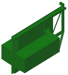
LUSAS model of
barge gate abutment with pile cap (blue) and steel bracing and
walling (green) |
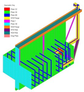
Colour coded plot showing abutment
steel plate thicknesses |
|
|
|
|
|

|
|
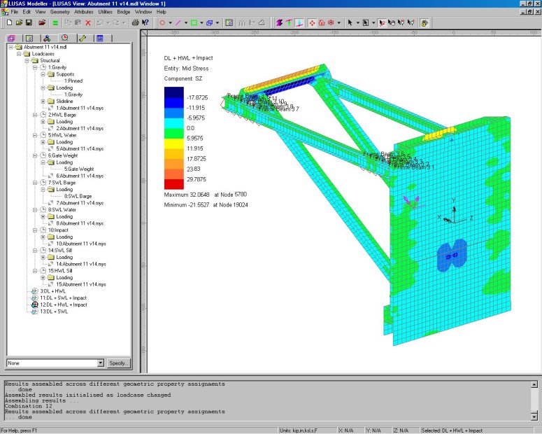
Typical load
combinaton stresses in a gate abutment structure |
David Stensby, Structural Engineer at
INCA said: "The barge gate design had to be done under very
tight schedule constraints. The fact that the diverse elements of
the abutment structure could all be modelled efficiently in the same
LUSAS model was especially useful, as indeed was the ability to
accurately model the water pressure loading on the barge
model."
Results
Results for each of the loadcases
were investigated and load combinations were created to derive
combined effects of different permutations of the self-weight, gate,
flood and impact loading. In areas of interest the LUSAS section
slice facility allowed localised stresses to be checked. David
Stensby confirmed the usefulness of the results: "The stresses
and deflections that we obtained from the LUSAS modelling allowed us
to adjust the gate design as necessary to meet the design
criteria."
James Costello, Project Manager at
INCA summed it up as follows: "LUSAS really shined on the
modelling and analysis of these steel barge closure structures and
as a result it helped us to meet the tight design schedule. The time
taken to model these structures in LUSAS was noticeably reduced over
that taken when we previously modelled similar structures with other
analysis packages."
 |
 |
| LUSAS
model of barge gate |
Barge
gate steel plate thicknesses used
(upstream and deck plates not shown for clarity) |
| |
 |
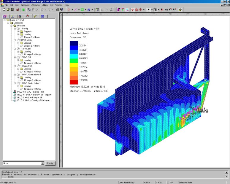
| Typical
load combination stresses in a barge structure |
"LUSAS really shined on the
modelling and analysis of these steel barge closure structures and
as a result it helped us to meet the tight design schedule. The time
taken to model these structures in LUSAS was noticeably reduced over
that taken when we previously modelled similar structures with other
analysis packages."
James Costello, Project
Manager, INCA Engineers Inc.
Find out more
Other LUSAS Civil &
Structural case studies:
|