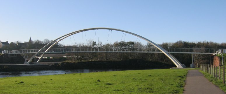
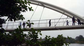
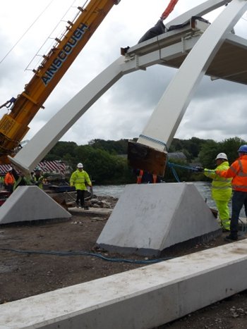
Capita Symonds was appointed by Cumbria County Council to carry out the outline design, a Category III design check and project management for the replacement Navvies Bridge in Workington, UK. The bridge comprises a twin ribbed untied bowstring arch steel superstructure, with an overall span of 84.8m, and carries cyclists and pedestrians over the River Derwent. To assist with its design and checking of the structure to the Eurocodes, Capita Symonds used LUSAS bridge analysis software. Overview The new bridge replaces a precast multi-span footbridge that stood at the same location, and which was partially washed away and damaged beyond repair during unprecedented flooding of the river in November 2009. The replacement arch structure spans 60m between arch springing points that are sited well above normal water levels and is better suited to withstand any potential future flooding that may occur. Funding for the new £1.7 million bridge included £375,000 from the charity Sustrans as part of a national project to provide walking and cycling routes for everyday journeys in communities across UK. At 3m in width the deck of the new bridge is almost twice as wide as the old bridge, easily accommodating its shared use. Demolition of the old bridge and the detailed design and construction of the new bridge was undertaken for the client Cumbria County Council by UK construction, infrastructure and design business Morgan Sindall.
Bridge construction The main inclined steel arch members of the bridge are of square hollow section with their principal axes rotated at 45 degrees to the main plane of each arch. The arch members taper from 600mm square at plinth level down to 500mm square at the first transverse-bracing level beneath the deck, further reduce to 400mm square at the level of the first hanger, and remain at that size for the central portion of the arch. Transverse upper bracing members separate the main arches at the central seven hanger locations. In all, nine inclined sets of 39mm diameter cables support the 300mm x 200mm x 16mm thick RHS longitudinal deck edge beams which are transversely braced at each lower cable fixing. The 16mm thick steel deck plate within the arch region is stiffened on its underside with 150mm x 12mm plates at approximately 800mm centres. Outside the arch region the deck beam and plate construction is lighter and the two 18m long back spans are supported at their mid-span positions by crossbeams sitting on V-shaped piers of 200mm square hollow section.
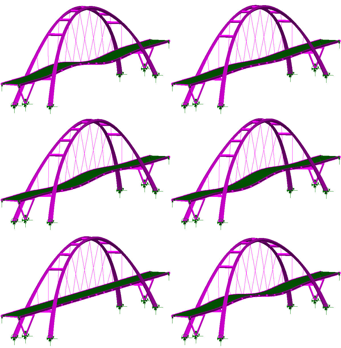
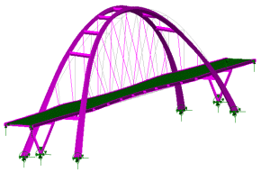
Modelling, Analysis and Results At the outline design stage, Capita Symonds built a variety of LUSAS finite element models to undertake linear, nonlinear buckling and dynamic analysis of the structure. A linear static model allowed for preliminary section sizing and for self-weight and cable tensioning effects to be investigated. For this, a custom-created spreadsheet helped to derive the cable load factors required in order to achieve the correct deck shape. Antonio Di Caprio, Project Engineer at Capita Symonds said "During the conceptualisation process with the appointed architect, Mr Ron Yee of Yee Associates, we used modal and transient dynamic analyses to ensure that the response of the structure would remain within the acceptable limits given by EN 1990, using pedestrian excitations from the UK National Annex to EN1991-2." A straightforward eigenvalue analysis identified the primary range of natural frequencies and eigenmodes for the structure. Subsequent investigation of the mass participation values for each frequency (which showed the magnitude and direction of model mass participation) and the use of the LUSAS animation facility helped identify the critical vertical, horizontal and twisting modes. The fundamental modes were used for more detailed pedestrian moving-load and steady-state analysis in accordance with the requirements of the UK National Annex to BS EN 1991-2 2003 using the LUSAS Pedestrian Load Wizard. Use of this wizard simplified and automated the creation of the loadcases required to model pedestrian groups passing across a structure. Lastly, a transient dynamic crowd loading assessment required the use of load curves to represent the imposed loading with respect to time and for this damping values as suggested by the code were used. This analysis was used to verify the comfort criteria levels by looking at the maximum vertical acceleration of the bridge deck. As a result, the ‘acceleration versus response-time’ steady-state response of the structure was obtained showing that the maximum vertical acceleration values were acceptable. Significant lateral mode frequencies were kept above the critical threshold value given in the UK National Annex to EN1991-2. A linear buckling analysis assessed the elastic critical buckling load factor and indicated that a geometric nonlinear buckling analysis also needed to be carried out.
"We used modal and transient dynamic analyses to ensure that the response of the structure would remain within the acceptable limits given by EN 1990, using pedestrian excitations from the UK National Annex to EN1991-2." Antonio Di Caprio, Project Engineer, Capita Symonds. Find out more
Other LUSAS Bridge case studies:
|
|
Software Information
|
|||||||||||||||||||||||||||||||||||
|
|||||||||||||||||||||||||||||||||||||
