Software Tour
Analysis and design capabilities
Analysis and design capability is dependent upon the
product in use. Particular LUSAS Bridge software products can be
extended by using software options. For details see the
Software Specifications.
The main analysis capabilities
are summarised here.
Multiple analysis
and branched analysis
When designing your
structure, more than one type of analysis can be defined and solved independently
from within one model using the multiple analysis and branched
analysis facilities. This means that, in most cases, there is no
need to create separate models and maintain clone copies of a model,
in order to analyse and view results for different analysis
requirements.
Analysis
branches allow the creation and solution of one or more sub-analyses
to investigate the response of the model at a particular loadcase or
"stage". Use analysis branches to:
- Carry
out a linear moving load analysis of construction equipment during
each stage of the construction of a segmental bridge deck.
- Perform
an eigenvalue natural frequency analysis or a buckling analysis
during construction.
- Perform
a phi-c reduction analysis to derive safety factors for a
geotechnical model from each stage in an excavation process.
- Perform
an earthquake analysis where gravity is applied in a static
nonlinear step, then the earthquake is run as a transient branch.
Several sample earthquakes may be run in each branch.
Linear static
- Stresses, strains, displacements, moments, shears and axial
forces that result from static loading are easily calculated,
displayed and output from any model.

|
Cable tuning analysis
Perform
linear and nonlinear cable tuning analysis. Use
nonlinear
cable tuning when geometric, material or
boundary nonlinearity may exist, and for use in obtaining pre-stressed
states of existing structures, or for modelling catenary effects.
Both cable tuning
analysis facilities calculate load factors for cables in order to
achieve defined target values set for various feature types or results
components. An 'exact' method, an optimisation facility and two
best-fit solution methods are provided.
|

|

Target values analysis
Use the target values post-processing
facility to vary load
factors in a linear analysis to try and achieve target values
specified for particular feature types or results components. The target values
loadset created is similar to a combination, but the load factors are
automatically calculated by the program in response to the defined
targets.

|
Buckling
Carry out elastic critical buckling, which is required for the calculation of
member resistances. Often it is also required by some codes to
determine if a second-order analysis needs to be carried out. If so, a
full nonlinear buckling analysis can be undertaken.
-
For existing
structures, assessment or load rating to regional design codes can
give conservative results showing they ‘fail’ buckling checks,
but detailed buckling analysis with LUSAS can often reveal
additional ‘hidden’ capacity and prove a load capacity.
-
For new plate
girder, box or tub girder bridge designs, linear and nonlinear
buckling analysis using LUSAS can investigate the girder stability
during erection, look at the effects of a slab casting sequence,
and also help to optimise the size of the web and flange plates,
bracing, stiffeners and position of any temporary supports used.
-
See Linear
and Nonlinear Buckling Analysis for more information.
|

|

|
Fatigue
Carry out fatigue
calculations using the total life approach. Express fatigue life in terms of the damage that is done to
the structure by a prescribed loading sequence or as the number of
repeats of a sequence that will cause failure.
|

|
Direct Method influence
analysis
Direct Method influence analysis is a
general and powerful way of calculating influences for line beam,
frame, grillage, slab and deck models. The effect of a specified point
load is assessed at each node or grid location on a loadable area of a
structure. Calculate the influences for any results entity /
component according to the elements used, as well as for user-defined
results components, for many locations and
quantities within a single analysis.
|

|

|
|
Direct Method Influence
definition
|
Direct Method Influence
assignment
|
|
Dynamics
LUSAS Bridge excels in solving seismic and
general dynamics problems. Straightforward
modal dynamics problems can be solved using Interactive Modal Dynamics
(IMD) techniques which are provided in selected LUSAS Bridge products.
The Dynamics software option
contains the facilities required to solve a wider range of dynamic
problems in the time domain with a step-by-step solution.
Additionally, by combining the LUSAS Dynamic and LUSAS Nonlinear
options both high and low velocity nonlinear impact problems can be
solved using either implicit or explicit solution techniques.
The natural frequency
of structures, the effect of dynamic loading, such as pedestrian
loading on footbridges and responses due to earthquake or impact
loading can all be readily calculated.
|
 |
|
|
|
|
Capabilities include:
|
|
|
|
-
Blast
loading
-
Ship impact
-
Seismicity
|
Forced response, vibration and transient dynamics problems can also
be solved, if you wish, by calculating the structural response for selected loadcases
using the Interactive Modal Dynamics (IMD) results processing facilities.

Interactive
Modal Dynamics (Modal superposition)
Interactive
Modal Dynamics (IMD) allows the natural vibration behaviour of a
structure to be combined with a loading regime in order to calculate
the dynamic response of a structure to a range of applied excitations.
IMD produces results an order of magnitude faster than traditional
time-step solutions. Multiple and more advanced loading events
(including moving loads and nonlinear behaviour) can be modelled with
the IMDPlus and additional software options.
|
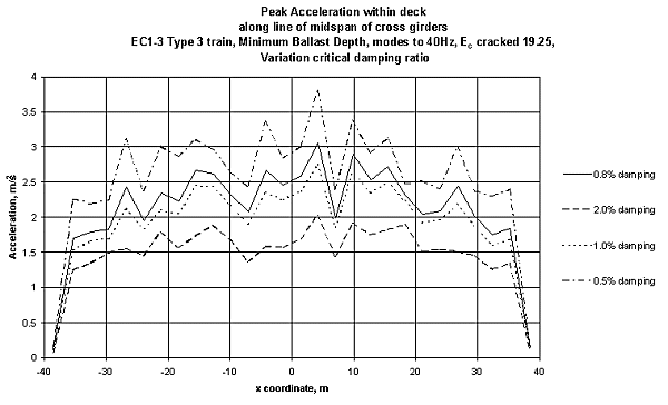
The
IMDPlus software option extends the
Interactive Modal Dynamics (IMD) techniques available in all LUSAS
products, and which model a single loading event in a single
direction, to allow multiple loading events with more advanced loading
conditions to be solved.
The
IMDPlus option is used for two primary uses: seismic response analysis
of 2D and 3D structures subjected to acceleration time histories of
support motion, and for the analysis of 3D structures, such as
bridges, subjected to constant moving vehicle or train loads, and
moving mass and moving sprung mass.
|

|


Staged
construction analysis
See LUSAS Bridge Staged Construction Modelling
Prestress
analysis
See LUSAS Bridge
Load types and combinations
Vehicle
load optimisation
See LUSAS Bridge
Load types and combinations
Nonlinear
An
analysis will often have to take account of nonlinear materials,
geometry, and support boundary conditions to accurately model the
structural behaviour. The LUSAS Nonlinear
software option provides the very latest powerful techniques for
solving problems having:
- Geometric
nonlinearity (large deformations, finite rotations and large
strains)
- Material
nonlinearity (concrete, steel, rubber and geotechnical material
models)
- Contact nonlinearity
(point and surface).
Local and
global nonlinear analysis with LUSAS helps ensure that bridges are
designed economically and safely for any imposed loading. Automatic
nonlinear solution procedures simplify the analysis process for
applications such as:
-
Modelling
lift-off
of bearings and halving joints
-
Lead-rubber
bearing analysis, bearing collapse
-
Elasto-plastic
large deflection plate buckling
-
Large
deflection cable analysis
-
Soil-structure
interaction / integral bridge design
-
Masonry
arch analysis
-
Time-dependent
dynamic analysis
-
Vehicle
and boat impact assessments
-
‘Push-over’
analysis
-
Large
deflection in cable structures
The Nonlinear option
can also be combined with the LUSAS Dynamic and Thermal / Field software
options to solve problems in which the effects of time and temperature
are important.

P-Delta
analysis
P-Delta analysis
is available for bar, beam, thick and thin shell, and 2D and 3D
continuum elements with GNL capability. P-Delta analysis is an
approximate geometrically nonlinear (GNL) analysis typically used to
take account of the interaction between vertical and horizontal (sway)
loading on tall, slender buildings. Vertical constant loads (usually
dead loads) are used to form the geometric stiffness (stress
stiffened) matrix for the structure; additional live load cases can
then be applied and load combinations used to capture the effects of
the interaction between lateral and vertical loading.
Creep
modelling
-
Concrete creep
including fib (formerly CEB-FIP) and Chinese model codes
-
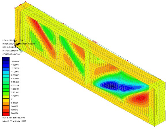
The image
(right) shows just a few exaggerated deformed shapes of a beam and
shell model used to carry out a staged construction analysis
(incorporating creep and post tensioning) to simulate the
construction of the deck of a proposed bridge across the
Mississippi River.
|

|
|
Soil-structure
interaction
-
Useful
geotechnical capabilities make use of a range of soil
models.
-
Residual
soil stress varying with depth can be accommodated providing
useful facilities for soil-structure interaction for integral
bridges and culverts.
-
Rock
joints, pore water pressure dissipation, consolidation modelling,
geotechnical problems involving long term excavation, construction
in clays, and temporary works can all be solved.
See Geotechnical
/ Soil-structure modelling
for more information.
|

|
Thermal
/ field analysis
The Thermal
/ Field software option contains extensive facilities for both
simple and advanced steady state, and transient thermal / field
analyses. By combining the LUSAS Thermal / Field option with other
appropriate LUSAS options, heat transfer due to conduction, convection
and radiation can be analysed. In addition, the effects due to phase
change of material may also be included.
|
Heat of
Hydration
Modelling
of heat of concrete hydration can be carried out for a variety of
cement types using the using the Heat
of Hydration software option. Effects due to the addition of fly
ash and ground granulated blast furnace slag can also be included.
When used in conjunction with Nonlinear, Dynamic, and Thermal software
options the heat of concrete hydration can be computed during a
thermo-mechanical coupled analysis and the temperatures and degree of
hydration can be read in to the mechanical analysis.
|

|
Rail Track
Analysis
When used
with the Nonlinear software option the LUSAS Rail
Track Analysis software option automates track/bridge interaction
analysis for light and high speed rail projects to the International
Union of Railways Code UIC 774-3. It allows you to automatically build
models from data defined in Excel spreadsheets, run an analysis, and
quickly calculate stresses and forces induced in the track from both
thermal and train loading. Parametric positioning of train loading is
supported, results graphs are automatically created and exported to
Excel spreadsheets, and code checking results tables are generated.

Faster
solution times
The Fast
Solver option comprises additional solvers for use with particular
LUSAS Bridge products.
-
The
Fast Multifrontal Direct Solver can provide solutions several
times faster than the standard Frontal Direct Solver for certain
analysis problems.
-
The
Fast Multifrontal Block Lanczos Eigensolver can, similarly, return
results.
several times faster than the standard Frontal Eigensolvers for
certain problems.
-
The
complex eigensolver provides efficient solutions for large-scale
damped natural frequency problems.
-
The
Fast Parallel Direct Solver and Fast Parallel Iterative Solver
will solve large sparse symmetric and non-symmetric equations on
shared memory multiprocessors.
Design
code facilities
Find out more
|
|
Software Information
|