|
||||||||||||||||||
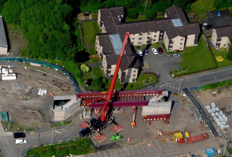
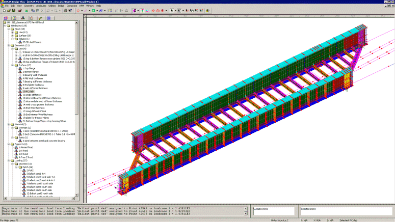
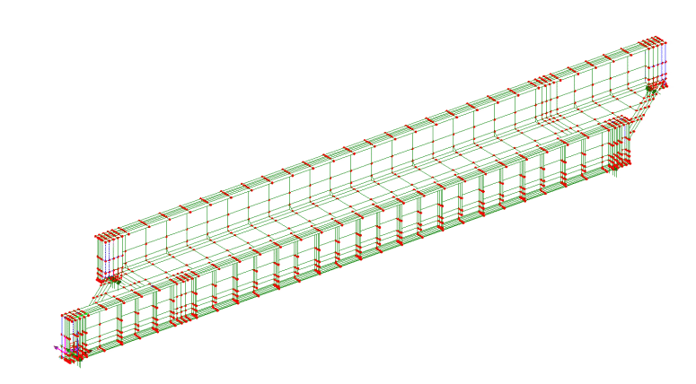
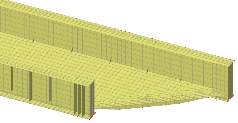
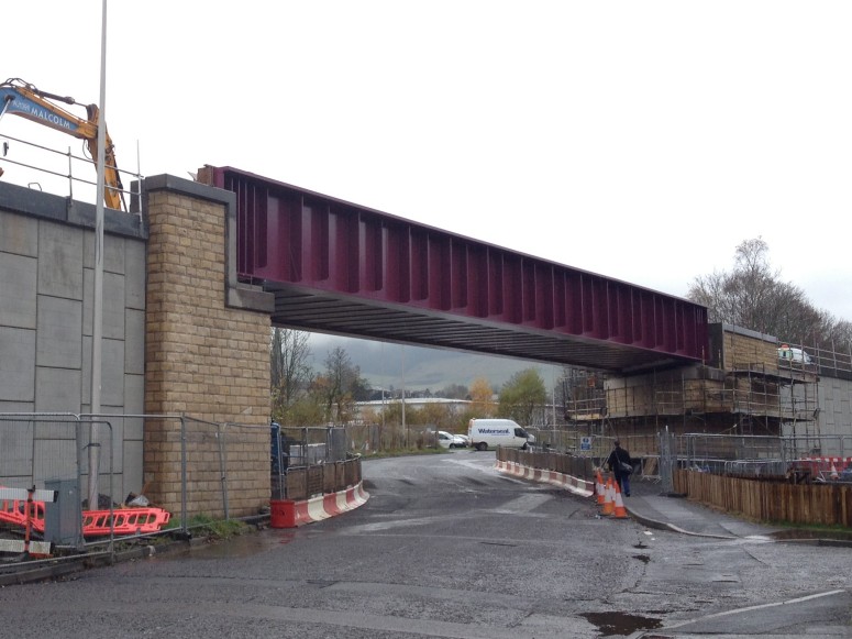
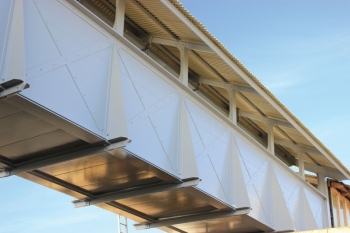
Bridge Construction The two main girders have an overall height of 2.7m and comprise doubled 60mm thick plates for the top flanges, 55mm thick plated bottom flanges, and 38mm thick webs stiffened with 50mm thick U-frame web stiffeners and 35mm thick intermediate stiffeners. Owing to transportation restrictions each girder was fabricated and brought to site in two lengths of around 26.6m and 12.4m, and supported on a falsework tower prior to being welded together. At bearing supports, three sets of 50mm thick stiffeners are used in conjunction with localised concrete infill to the inside of the girder at this location, as based on Network Rail standard, to facilitate waterproofing details, maintain the ballast, and provide the necessary stiffness required. The filler deck comprises 356x406x287 Universal Column section cross-beams and a 250mm thick reinforced concrete slab with upstands that are connected to the main girder webs with studs. End trimmer beams are welded to the end plates, which, in turn, are welded between the end bearing stiffeners. A 700mm wide walkway is connected to the south side girder. Modelling with LUSAS A 3D finite element model of the superstructure was developed in LUSAS using shell elements to represent the main steelwork and reinforced concrete slab. The cross girder webs and end trimmer webs were also modelled by shells, with top and bottom flanges represented by beams with appropriate section properties. The reinforced concrete upstand between bearing stiffeners and jacking stiffener was represented by solid elements, which were connected to their respective steel elements in contact via joint elements. Structural design was based upon a rail traffic design speed of 75mph.
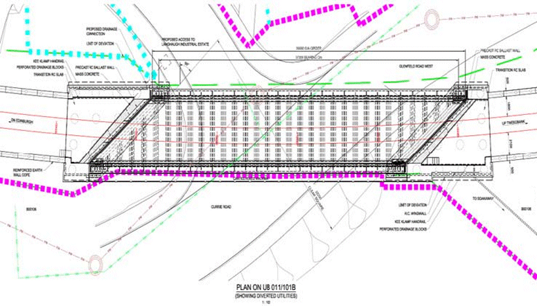
Typical bridge development model Network Rail standard drawings for half-through steel girder decks with a 50 degree skew angle dictate that from 8 to 10 bearings are used. For this 'standard' design, each main steel girder seats onto two large bearings whereas each end trimmer is independently supported on 2 or 3 bearings depending on the end trimmer length. By using LUSAS, Atkins showed that by connecting the end trimmer to the main girders, the number of bearings used could be reduced from 10 to just 4, and this was adopted in the final design.
Model geometry and mesh arrangement
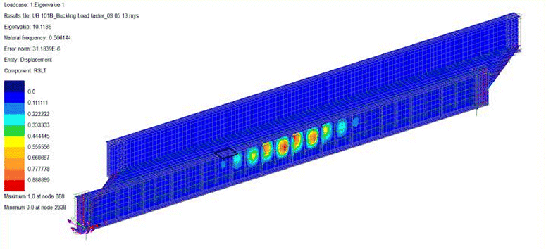
Detail of meshing showing end trimmer beam A linear eigenvalue analysis was carried out in accordance with Network Rail Standard NR/L2/CIV/003/F1993. This document, which provides Network Rail's instruction and guidance on the selection of the open options/choices permitted by BS EN 1993: Eurocode - Design of Steel Structures, does not allow second order analysis under a CAT II check, and therefore a critical load factor of greater than 10 was required.
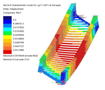
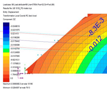
Load factor modelling The maximum twist of the track gauge was accurately verified in accordance with BS EN 1990:2022+A1:2005 A2.4.4.2.2 using displacement contour plots. The interaction between track and structure was considered in accordance with EN1991-2:2003 clause 6.5.4.6.1 using the simplified calculation method for a single deck given displacement criteria.
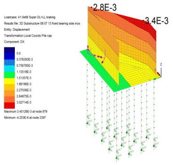
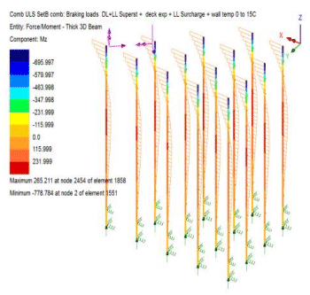
Another 3D LUSAS model analysed the piled substructure. Thick shell elements modelled the abutment, wingwalls and pile cap, and beam elements modelled the pile group. The horizontal spring values were determined using the method set out in "Foundation Analysis and Design 5th Ed", Joseph E. Bowles, with additional guidance from the LUSAS technical support team.
In summing up the modelling and analysis carried out, Dr Fabien Rollet, Senior Engineer at Atkins said: "Carrying out a superstructure and substructure interaction analysis allowing for accidental loads and deck twist limitations in accordance with the Eurocode and Rail standards can be extremely laborious using 2D or 3D grillage models, and necessitates a large number of additional hand calculations based on previous standards. Generating a full 3D finite element model using LUSAS allowed us to complete the design rapidly and efficiently, and optimize the section sizes with high precision." The construction of Borders railway is scheduled to be completed in the summer of 2015, and the line is expected to enter service in September of the same year.
"Carrying out a superstructure and substructure interaction analysis allowing for accidental loads and deck twist limitations in accordance with the Eurocode and Rail standards can be extremely laborious using 2D or 3D grillage models, and necessitates a large number of additional hand calculations based on previous standards. Generating a full 3D finite element model using LUSAS allowed us to complete the design rapidly and efficiently, and optimize the section sizes with high precision." Dr Fabien Rollet, Senior Engineeer, Atkins
Share this article
Find out more
Other LUSAS Bridge case studies:
|
|
Software Information
|
||||||||||||||||
|
||||||||||||||||||