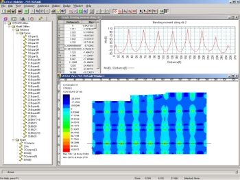
Previous inspections In the late 1990s, following condition surveys and inspections, the bridge superstructure was assessed to UK code BD21 and found under strength. The survey and assessment reports noted that the condition of the HBs was good with no visible signs of distress. However, it was assumed that the HBs did not carry any loading and that all load was carried by the more recent deck system comprising the UCs. Extensive rehabilitation and strengthening works were envisaged following the failed assessment. In view of the location of the structure in a busy urban environment significant costs were foreseen primarily due to extended railway possessions and road traffic management during implementation works in addition to major disruption to the road and rail traffic systems. Detailed re-inspection In 2002, Tony Gee and Partners were commissioned to carry out detailed condition surveys of the bridge and to re-assess the superstructure in order to possibly reduce the scope of rehabilitation works. A review of past reports and archive material was conducted and areas of previous studies were identified that needed further investigation. Bridge inspections using flexible endoscopic equipment to view previously unseen areas of the structure were almost startling. It was found that the packing placed in order to achieve load transfer between the old and the new deck systems was either missing or had become dislocated in a substantial part of the deck that was inspected. As a result, and contrary to what was presumed in earlier reports and assessments, there was little contact between the old and the new deck systems and in effect all dead and live loading was being carried by the old Hobsons beams. The latter installed UCs hardly appeared to carry any loading other than their self weight. Feasibility studies Following the bridge inspections preliminary calculations investigated the feasibility of using a more satisfactory load sharing scheme. This primarily envisaged installing specially seated jacks at predetermined locations between the old and the new deck systems and inflating them to pre-calculated loads The objective being to achieve a certain degree of load transfer from the old system to the new system and to ensure a ‘composite’ interaction between the two deck systems for live loads. Modelling with LUSAS It was agreed with the client, Birse Rail, right at the onset that given the complex nature of the scheme it was essential to make use of a powerful finite element program in order to conduct the analytical study of the proposed scheme. LUSAS Bridge was used for all phases of the analysis from the simplified single-element models of various structural components to the detailed three-dimensional space-shell models of the superstructure. The steel Hobsons beams were modelled using 3D shell elements while the UCs were modelled with 3D beam elements. By using the shell elements it was found feasible not only to model the true geometry of the old deck but also to study the stress distribution in the HBs under various loads. This approach also allowed the modelling of the shared interaction of the common tension flanges of the HBs which would have been more difficult to idealise in a grillage-type analysis. All analysis was carried out in the linear elastic domain with solutions aimed at investigating upper-bound and lower-bound possibilities of stress distribution under various loads and load transfer constraints. In this regard particular attention was given to the modelling of the live load transfer mechanism provided by the installation of the jacks. The model was gradually upgraded during the course of the analysis to include the various features proposed in the rehabilitation works. Sameer Khan, senior engineer at Tony Gee & Partners said: "The emphasis of the analytical study was to explore various possibilities within the constraints of the project and not necessarily devise one unique solution. In this regard LUSAS provided an efficient FEA tool in terms of the wide range of modelling possibilities it allowed. We found it quick and simple to upgrade an existing model in order to include new features or de-activate existing ones within a 3D model. In addition the results processing facilities were particularly useful in identifying the critical areas of the deck."
Conclusion Following the analytical studies it was shown that the two deck systems could be made to achieve a satisfactory level of load sharing and with minimal rehabilitation works the superstructure could be strengthened to carry the 40 tonne loading to UK code BD 21/01. The analytical study confirmed that rehabilitation works envisaged after the earlier failed assessment could be reduced substantially with associated savings in time and costs. "The emphasis of the analytical study was to explore various possibilities within the constraints of the project and not necessarily devise one unique solution. In this regard LUSAS provided an efficient FEA tool in terms of the wide range of modelling possibilities it allowed. We found it quick and simple to upgrade an existing model in order to include new features or de-activate existing ones within a 3D model. In addition the results processing facilities were particularly useful in identifying the critical areas of the deck." Sameer Khan, Senior Engineer, Tony Gee & Partners Find out more
Other LUSAS Bridge case studies:
|
|
Software Information
|
||||||
|
 Case Study


