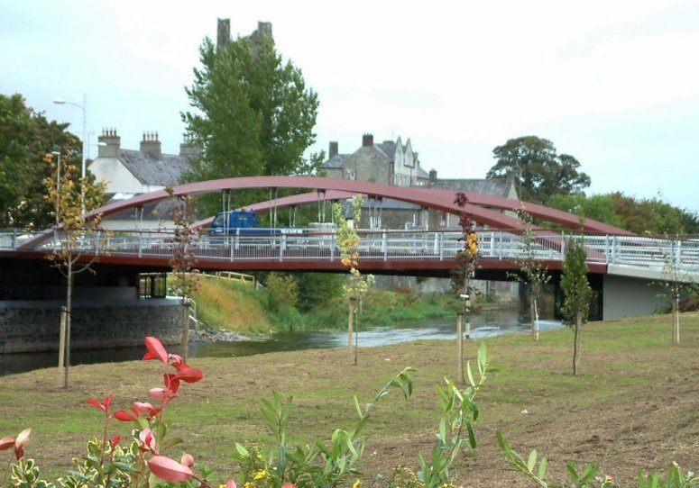
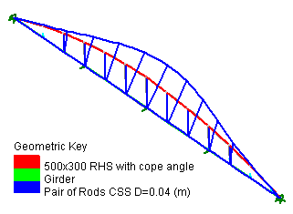
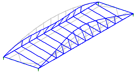
The final and possibly most important stage of the preliminary design was the buckling analysis. UK design code BS5400 Part 3 gives a table of effective lengths for compression members, all of which are rather conservative, but allows the designer to determine the effective length by an elastic critical buckling analysis. LUSAS calculated the first few mode shapes and the effective length and critical buckling load was found. 3D detailed analysis A complete elastic analysis was carried out on a 3D line beam model with the deck modelled with thick shell elements. Live loading, temperature loading, and the effect of a collision on the arch rib were all analysed. From this, it was found that the tensile forces in the tie beam were shed to the composite concrete deck and as a result the girder size was reduced and additional reinforcing steel was added to the deck to take the tensile stresses. This made the deck monolithic with the tie beam, and torsionally stiffened the girder as a result.
It was considered that the linear buckling analysis from the two dimensional model had over-estimated the critical buckling load so this was recalculated for the 3D model with more accurate modelling of the end fixity. A full geometric nonlinear buckling analysis investigated 2nd order effects of loading the deck and from the load cases considered it was seen that loading the full span with a Uniformly Distributed Load caused the greatest lateral deflections of the arches. A comparison of the effective lengths from the 3D linear and nonlinear analyses gave very similar results of 12.7m and 12.5m respectively. Based on these values a maximum allowable compressive stress of 212N/mm2 was obtained for the steel type used.
Local modelling While the 3D line beam model was satisfactory for the design of individual members, more detailed local models were required for complex fabricated connections such as the arch/girder connection above the bearing and for the arch/tie rod connection. Forces and moments derived from the 3D global model were applied to the local model allowing stresses and shear distribution in these connections to be easily seen and economical weld sizes obtained.
"LUSAS was used throughout the design, from preliminary sizing of members right through to the detailed design of the more complex fabricated elements. It helped us to provide the client with an efficient, aesthetically pleasing structure." David Doyle, Structural Engineer, Roughan & O’Donovan Find out more
Other LUSAS Bridge case studies:
|
|
Software Information
|
||||||||||
|


