|
||||||||||||||
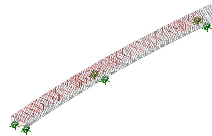
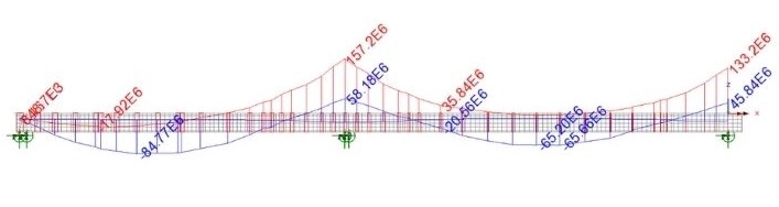
Traffic loading � vehicle load optimisation The identification of the traffic load positions that give the maximum / minimum design actions on the various elements of interest was carried out through an automated procedure involving the processing of the surfaces of influence of the various stress characteristics, at the points of interest using a �Direct Method Influence� (DMI) analysis. Once done, a Vehicle Load Optimisation analysis found the most unfavourable traffic load positions. Axial force, shear force and bending moment at the points of interest in a beam-shell model are obtained by integrating the results on �slices� through the model that are placed independently of the mesh. From these, influence surfaces, defined in order to evaluate the maximum / minimum bending and shear stress on the most stressed longitudinal beam can be calculated.
Results visualisation The �slices� allow the forces and moments in sections to be obtained at chosen locations according to needs and make the visualisation phase of the results fast and concise even if only a small number of �slices� are used.
Diagam of My for the external and intermediate girder for the fundamental ULS. Definition of verification sections in PontiEC4 The definition of the slices in LUSAS allows for automatic creation of the verification sections in PontiEC4, which nests them in the corresponding segment of the steel beam, and loads in the corresponding design forces and moments. If not used, the sections and segments must be defined directly in PontiEC4 and the design forces and moments imported from an Excel file.
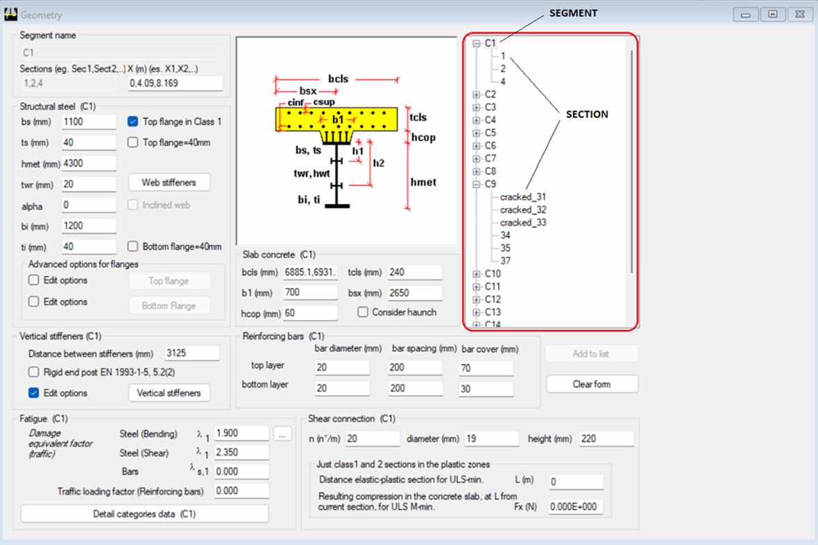
PontiEC4 geometry window - Section definition Import data from LUSAS and geometry definition The most straightforward use of PontiEC4 is for checking of all sections of a single longitudinal beam. Using the x coordinate of the section in a longitudinal beam, PontiEC4 associates with the section the width of the slab that is collaborating and is to be considered in the checks due to the shear lag effect.
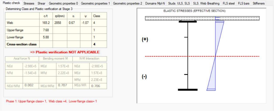
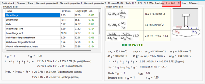
Classification and plastic check of the section on pile support axis P1
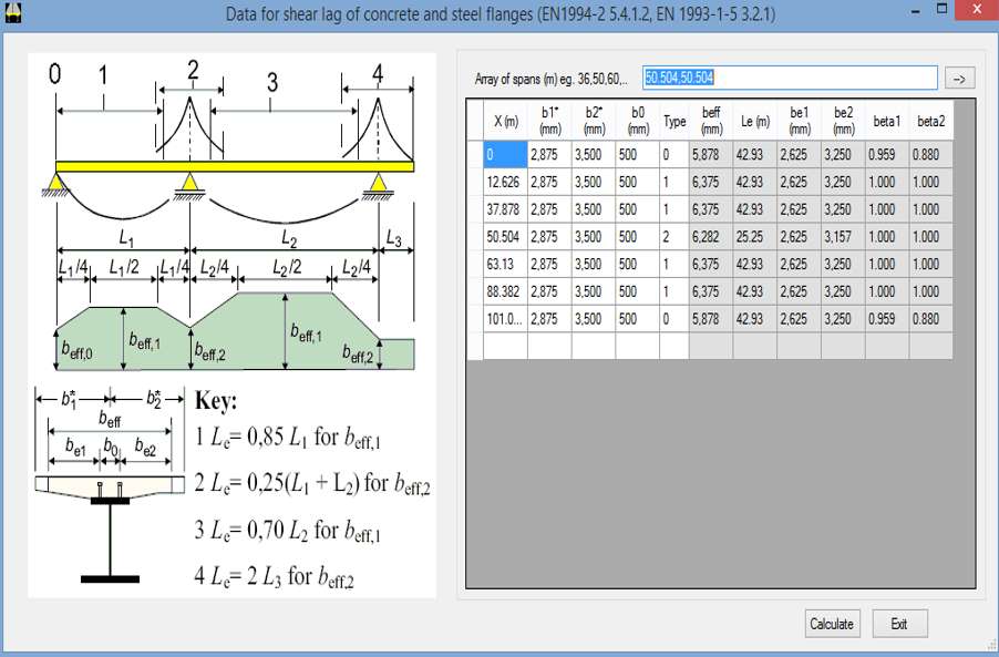
Shear lag data dialog in PontiEC4 ULS, SLS & fatigue calculations in PontiEC4
All check results are available as graphs of utilization ratio in all sections along the beam into analysis.
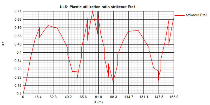
Plastic utilization ratio eta1 along 2 spans of the viaduct. A multi-page form gives a summary of results of the checks made for each section.
Fatigue L.S. details check on the section at pier 1.
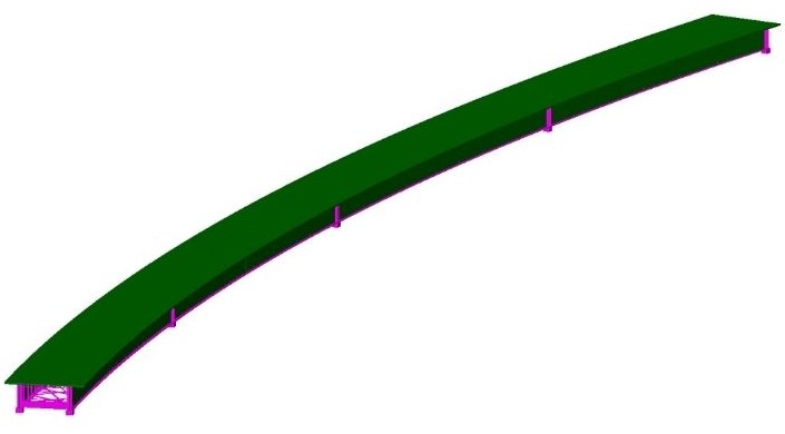
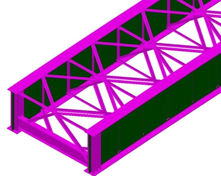
�The possibility of obtaining force and moment diagrams from a series of sections of a beam-shell model, coupled with the availability of generating influencing surfaces for the same sections, allowed us to model the bridge with transverse beams and torsion braces in their real position, fully considering the effects of the curved plan. The use of LUSAS with PontiEC4 allowed a fast and excellent optimisation of structural steel and of reinforcement steel.� Federico Durastanti � Technical Manager Sintagma srl (Perugia - I) Modelling approaches possible Finite element modelling of steel-concrete bridge decks typically involves the use of one of the following methods :
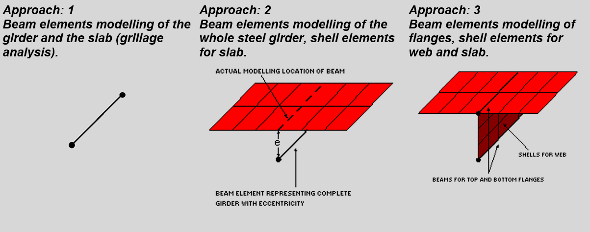
Methods 2 or 3 are easily achieved by finite element software. They also permit dealing with curved girder structures (where significant torsional stresses arise) and when design stresses in any bracing are to be obtained directly from the model. Share this article
Find out more
Other LUSAS Bridge case studies:
|
|
Software Information
|
||||||||||||
|